On Sunday 11th August at Flight Refuelling ARS we opened gates for their 40th Hamfest!
We always book good weather, and to be fair we do get it most years. This year was no exception, warm and sunny with a little cloud to keep the temperatures comfortable. Big Chief’s ice cream van did a very good trade as well.
With traders and local radio clubs and organisations in the traders area there were quite a few bargains to be had, along with a lot of banter between folks who turn up year after year and catch up with friends. The separate car boot area is as popular as ever, and this year saw a lot more radio-related offerings at this end of the field. There were a few traders in the main building as well, and the RSGB book stand too!
FRARS HQ was open for visitors, with demonstrations of our EME (Earth – Moon – Earth) system and the 12’ diameter dish antenna. Our ever-popular ‘treasure’ stall outside the HQ was a good attraction as well.
A selection of talks and presentations in the lecture room proved as popular as ever.
The South West Model Railway Club, who have the building behind FRARS HQ, were open for visitors as well, and they gave the first talk of the day.
We were pleased to see an increase in visitors this year and received a lot of good feedback from them as they left.
Hamfest 2025 will be held on Sunday August 10th – we look forward to seeing you there!
Recently the FRARS 3.4 GHz system has undergone considerable work to upgrade its performance for EME.
The system now has a fully GPS referenced, frequency locked transverter based arrangement, based on a Down East Microwave design.
A 3.4 GHz LNA has been acquired from Sam G4DDK and a waveguide based Interdigital filter has been produced to provide roofing bandpass characteristics. This is followed by a second stage GaAsFET LNA feeding the transverter.
The power amplifier is based on an identical pair of 30W ex Telecom modules, each supplied by a head plate mounted 240 volt mains input switched mode power supply. After a lot of work it now outputs approximately 55 Watts of CW. Shack based power monitoring is available and the complete system is driven from an IC746 and WSJT-x.
During the enhancement process, HB9Q was worked just before 3.4 GHz was withdrawn by the Swiss authorities. (see separate article) and now several other QSOs to other countries have been logged using the enhanced system.
The final act to complete the system has been to mount the umbilical connected transverter onto a new weatherproof plate housing at the rear of the dish.
EME (moonbounce) activity sessions at the club for EME are shown below. Visitors are welcome to come to the club and see what EME is all about. However, it is advisable to check first, in case of last minute changes, using the contact form here.
Gareth (G0MFR), John (G0KFM), John (G4POF), Tony (G3PFM) and Dave (G0FVH) gathered at the club over the weekend 9-10 December for the ARRL 10 m ARRL contest! Good to see the HF shack busy over the weekend. Pork pies were consumed and much DX was worked!
The band switched on at sunrise with early openings to Asiatic Russia and northern China. The JA and ZL paths never opened this far north (I tried). The VK path soon opened and John (G4POF) worked several stations on SSB in the morning with real S9 signals. We picked up some nice south east / mid Asia multipliers during the morning.
The north / south path was open during the day with South Africa & Kenya on CW and Namibia & St Helena on SSB. Working European multipliers was very difficult apart from some very unreliable backscatter propagation. Even the big stations in north Africa were difficult, with the skip going over their heads.
About mid-day the South America path was hammering in. Dave (G0FVH) worked several Argentinian stations that were absolutely end stopping.
Very good opening into southern Caribbean on the second day (much stronger than on the first day): Aruba, Curacao, French Guyana, Trinidad, etc, etc all 1st call S9++.
After lunch the band was completely open to the US with stations to work every few hundred Hz from 28.000 to 28.120 on CW and similar on SSB starting about 28.280.
The real polar paths into KH6, KL7, etc didn’t really happen but in general 28 MHz was absolutely hopping and it was a fun contest. It was good to see that G4R has been well used in the last few months.
Over the weekend of 25th/26th Nov FRARS entered the CQ World Wide CW contest. This is a 48 hour CW contest with the aim of making as many contacts as possible. Every DXCC country and CQ zone is a multiplier to boost the score.
We started at 00:00z Our first contact was Romeo YO4RDW. We worked each other on 5 bands over the weekend. Conditions were very good especially on the higher bands. A total of 127 DXCC countries were worked including over 100 on 28MHz and 21MHz.
We made over 1400 QSOs with a score of over 1.5 million which put us top England station in the multi operator/single TX category. Romeo was top single operator in Romania and very high in the Europe rankings.
A great result for club members and FRARS. The rotator is now fixed and we have some ideas for LF antennas so hopefully we’ll do better next year.
Medii is the name of the software that tracks the FRARS 12 foot (3.4 m) dish with high precision onto the moon for the purpose of EME (Earth-Moon-Earth or moonbounce communications – bouncing radio signals off the moon). Medii is named after/for Sinus Medii (a crater near the centre of the moon).
This is a potted history of the Medii development and is based on a presentation which I (John M5AHQ) gave at the FRARS club in 2023.
EME had been running at the club for some years. A number of people have been involved with the project in that time, lead by the pioneering efforts of Julian G3YGF and John G0API. A history of the whole project can be found here.
This article does not cover any of the radio or modulation aspects or the EME contacts. They are better covered in the whole project history above.
I was asked by Jules G0NZO if I would write the software to automate the tracking of the dish onto the sun. If I’d known then what I know now then I would have run a million miles and said “********”. expletive deleted.
Tracking is about much more than software as will become clear. Unfortunately software does not make tracking any more accurate. If anything it makes it a little worse.
The Problem(s)
The moon, as we know, is a moving target. We need to track the moon with an accuracy of about 0.1 degrees in both Azimuth and Elevation.
The beamwidth of the dish is about 0.5 degrees. The moon, as seen from the earth, is 0.5 degrees wide so the FRARS dish nicely illuminates the full surface of the moon without wasting significant energy with a wider beamwidth.
However determining the position of the moon needs to be handled to an accuracy of about 0.01 degrees in order to achieve a full system accuracy of 0.1 degrees. More on this later.
Similarly the position of the dish needs to be determined and this needs to be better than 0.1 degrees accuracy.
There is half a ton of metal to steer. The club dish isn’t a sheet of pressed steel.
The gearbox, or rather gearboxes, have 6 degrees of backlash in azimuth.
The dish has to handle and compensate for movement due to windage.
The dish has to be aligned mechanically to ensure that movement in azimuth and elevation is true movement in azimuth and elevation. A mis-aligned dish will cause one to affect the other and degrade the operation of the automated system. This will become clear later.
How Did It Use to Be Done
Originally the dish had a boresight camera which pointed at the sky in roughly the same direction as the dish. There was a box (not actually a joystick) with 4 buttons on it which would adjust AZ and EL via motors on the back of the dish.
The dish would initially be lined up onto the moon (more about this later) and the moon should appear near the centre of the display. Once peaked a circle would be drawn around the moon with a marker pen on the TV monitor.
One person would then sit in front of the monitor and nudge the dish in AZ and EL to keep the moon in the circle. This was tedious job.
If clouds appeared in front of the moon then the task became quite difficult and it had to be based on a mixture of judgement, moon noise on the radio and a lot of luck.
Automation was clearly needed.
The Solution
The solution, or at least the chosen solution is, well, a classic linear closed loop control system. More details of the individual parts will come later. In summary…
Software is used to determine the moon’s current AZ and EL from our location on earth. Position sensors on the dish give a measurement of the dish’s current position. The two are subtracted to give an error signal which is passed into the control block.
The control block uses this error signal to provide the appropriate drive to the motors and the gears that drive the dish.
When the error reduces to zero (prediction and position are the same) then the motors stop.
Hardware / Software Split
Here the hardware and software split is shown.
The moon prediction, error signal generator and most of the control blocks are handled in software on a Raspberry Pi 3B.
The generation of the conditioning signals for the motors drives is very time critical and is handled in real time processing in a Raspberry Pi Pico.
The motor drive units generate about 80 Volt square waves to drive the motors.
All the parts of this block diagram (hardware and software) are expanded upon below.
Azimuth
The picture shows the dish drive shaft on the left, the two azimuth gear boxes below and the position sensor middle top.
This may all look a bit “Heath Robinson” and perhaps it is. However the mechanics of the system are easily capable of driving the dish and give the required accuracy. A highly engineered solution here would have been outside of the range of the club’s budget.
There are two gear boxes in series which, between them, give 1,015:1 reduction from the stepper motor at the bottom centre right of the picture.
The gear boxes give 6 degrees of backlash, which might seem to be a problem in a system requiring 0.1 degrees of accuracy. However, the moon, and other objects in the sky, always pass clockwise. So, it is possible to track by always driving on the same face of the gears. Only when parking the dish, or driving to a new position, is reverse tracking necessary.
There are a pair of counterweights, not shown in the picture, which hold the dish on the same driving face of the gears.
The position sensor at the centre top is a “selsyn”. The selsyns caused many problems and were later replaced. More about these later.
Elevation
The elevation gearing is a little different to the azimuth. The stepper motor is at the right hand side of the picture and the gear box is a long lead screw shown rising at 45 degrees to the top of the dish.
The gear box gives a maximum gearing ratio of 4,188:1. The nature of this type of gearing is that the gearing ratio is not constant for all elevation angles.
This system suffers from considerable mechanical resonance problems in the dish and lead screw. A consequence of this is that the stepper motor can only be driven to a maximum of 7,000 pulses per second before the dish starts to shake violently. Indeed the mechanical resonance changes for different angles of elevation and the elevation drive has to be profiled in the Medii software to avoid these resonances.
There is a brown protective covering shown and a similar one on the other side of the dish. One of these holds the elevation “selsyn” sensor and the other holds the more modern sensor which replaced the selsyns due to the problems which will be described later.
The picture also shows two counterweights which balance the dish in elevation and make driving the dish in elevation require much less force than would otherwise be the case.
Motor Drives
The stepper motors are driven by pulses from commercial motor drive amplifiers at 80 volts peak to peak. These drives need to handle high short instantaneous current surges. Each pulse produces a small movement in the dish in azimuth / elevation. Consequently the drives run quite hot.
The 80 v square waves with high current spikes from these drives produce a significant amount of RF noise. When first tested these drives would produce a local S9 noise across the HF bands and up to 70 MHz. Julian G3YGF spent a lot of time working on this to make the drives fully EMC compliant.
In the early incarnation of the system, the drives were in turn driven with small signal pulses from a PIC micro-controller using software written by Andy G4JNT, taking a demand value coming over an RS232 link from the main controller. This part has now been replaced, see just below.
The PIC micro-controllers and Andy’s software probably gave the best achievable performance with the technology that was available 20 years ago when this part of the system was first built.
PIC Micro-controller Replacement with Raspberry Pi Pico
The PIC Microcontroller was replaced with the Raspberry Pi Pico to provide the small signal pulses to the motor drives. These really are nice little devices and very capable with a number of built-in peripherals and very useful hardware state machines.
One of the built in peripherals is a pulse width modulation (PWM) output capable of producing 5 HZ to 60 MHz.
The hard real time control software was written, as part of the Medii suite, to run on the pico.
As well as the functionality described just above it also now provides the ramping up and down of the motors which gives us very granular control of the dish movement. It became possible to “tune” the software on this device to adapt to the mechanical response of the dish.
Medii Control Hardware
The main part of the controller hardware in the control loop is a Raspberry Pi 3B
The hardware has to provide the facilities for the MEdii software to implement the controller, motor drive communication, Position sensor communications, RS232, ethernet and a position display on an LCD display.
The Medii controller software description follows later.
Where Is The Moon?
The moon is a moving target. It orbits the earth. It takes approximately 25 hours between zenith points (highest point in the sky) on consecutive days. So, the high points get later by about 1 hour each day. It takes 27.322 days to orbit the earth. It is tide locked to the earth so we always see the same part of the surface. Looking down from the north both the earth and the the moon rotate anti-clockwise. It’s orbit is also elliptical.
The calculation is horrible!
We didn’t try to solve this from first principles but instead looked for others who had. We initially used a piece of software written by John Magliacane KD2BD, which in turn was based on some Visual Basic embedded in a spreasdheet which had come from NASA. Unfortunately this didn’t provide us with the level of accuracy that we were looking for (about 0.01 degrees).
We later found a piece of software from Thomas Alonso Albi of the Spanish space centre. This software did provide us with the accuracy that we needed and it was built into the Medii software. I don’t claim to understand how the algorithm works in this software. However, we’re grateful to Thomas for making this software freely available.
Position Detectors (Selsyns)
These position detectors (selsyns) were originally used to determine the position of the dish. Indeed they predate the Medii software by some considerable time.
A selsyn is fundamentally a synchronous motor in reverse. They were used on aircraft for position sensing. They have a stator winding which is energised at 26 V RMS 400 Hz. There are two rotor windings, 90 degrees apart. The amplitude and phase of the induced current in the rotor windings can be used to calculate the armature position.
These units can be made to give a very accurate position indication over a small range of movement. However they don’t work well over a large change of movement and in particular, suffer from dropouts at the cardinal points where the amplitude of one or the other signals from the rotor windings falls to zero.
Original Position Decoder
NEC made this decoder to work with the selsyns. Along with the selsyns, the decoder was obtained from a site decommision and was adapted to our use.
As previously said, the system was designed to provide high accuracy over a small range. The decoder has 20 trim pots on the analogue channels to calibrate out the errors over this small range. Over a large range the decoder was much more inaccurate (+/- 1.5 degrees at the worst points).
As well as the inherent errors it introduced it is likely that the components in the analogue circuitry had drifted over the years and introduced more errors.
Indeed the errors were so big in the position sensing system we were unaware that the errors were also masking errors coming from the alignment of the dish.
Rebuilt Position Decoder
The original NEC decoder was seen as the weakest link in the position decoding. I built a modern replacement for that decoder using two soundcards to do analogue / digital conversion, a Raspberry Pi and some op-amps for the higher voltage analogue circuitry.
I also wrote software for converting between the digitised inputs and the absolute position output. This included writing some some very deep digital bandpass filters in software to reduce the system noise to an acceptable level to produce a resolution of 2 decimal places in the position readings.
I can’t overstate the amount of digital filtering required to reduce the noise to acceptable levels. The digital filters in software had 200 taps on the filters.
A resolution of 0.01 degrees was achieved. However the inaccuracies in the position readings over a wide range were just as bad as with the NEC box described above, about +/- 1.5 degrees. In reality not all of this error was down to the position sensing. We would later discover that the mechanical alignment of the dish was also introducing significant errors.
After months of work trying to improve the accuracy in this system we eventually abandoned both the selsyns and analogue decoders in December 2021.
This was a real low point in the project, both in terms of technology and team cohesion. We had largely spent two years going down a blind alley and should have abandoned this solution 18 months earlier when it was determined that making this tracking technology work was going to be an uphill struggle.
New Optical Digital Encoders
These digital absolute position encoders are manufactured by the German company “Sick”. The normally sell for £700 each and we needed two. Not a cheap solution. However we managed to purchase a pair second hand for very much less.
The absolute position encoders use optical techniques internally and provide 262,000 points per revolution. The internal software processing in them gives a resolution of better than 0.01 degrees and a repeatable accuracy to any point of 0.04 degrees. This gives us the accuracy that we need.
The interface to them is ethernet using an industrial automation protocol called CIP which operates over TCP/IP. Unfortunately the specs for CIP are not published, other than in a closed industry forum. Consequently I had to reverse engineer the protocol using snippets of information that I could find on the web and by using Wireshark. This was a real pig and I came close to abandoning these device at one point. However I did get there and we now get position readings from these devices.
The Medii software was modified to work with these devices and the improvement in accuracy was immediately obvious. However it also, for the first time, revealed the errors that we were seeing in the mechanical system. More on this later.
Software Core of The Medii Controller
The software core is the block marked “Control” above. This is fundamentally a “proportional controller” within a closed loop system.
The gain of the system was set such that the system was slightly under-damped, which generally gives the quickest time to reach the demanded position.
Job done? Absolutely not!!!! See the next slides.
Backlash / Azimuth Counter-Weights
As previously stated, there are two gear boxes in series (with a gear ratio of 1,015:1 and 6 degrees of backlash) along with a stepper motor in the blue housing. Alongside you’ll see one of the azimuth counter-weights inside the metal basket. There is another on the far side of the dish.
Despite the backlash, the objective is to track objects across the sky in a clockwise direction. The mechanics have been designed to overcome the backlash for this purpose. Drive is normally always in one direction when tracking. When slewing back to another position the counter weights pull the dish back to prevent having to drive through the backlash. However this is just part of the story. See the diagram below.
This is a very crude model of a gearbox which shows the backlash. When the gears are engaged face A-A or face B-B then the gears are being driven but these is a gap between A-A and B-B across multiple gears and this leads to the 6 degrees of backlash that we see.
As previously stated, driving clockwise in not a problem because the counter-weights will hold the gears on B-B. However when slewing anti-clockwise, the drive will move into the backlash until the engagement is A-A. This effectively means “crashing” through the backlash which over time will damage the gearboxes and weaken other parts of the mechanical system.
A mathematical model was created and simulated in software to show the effect of driving down and to determine how far through the backlash the motors had driven. This would allow for some deceleration as A-A is approached until the natural speed of anticlockwise movement is matched (due to the effect of the counter-weights pulling the dish round). This would allow a soft landing on A-A.
This mathematical model was built into the Medii software and, amazingly, this technique works remarkably well.
Mechanical Resonance in Elevation Movement
The diagram shows the lead screw on the Elevation drive.
Unfortunately there is a mechanical resonance in the whole system which manifests itself when moving in elevation. The frequency of this resonance varies with elevation. Also, the speed of elevation drive to reach this resonance varies with elevation.
Driving elevation at full velocity would shake the dish and the mounting to pieces.
The elevation velocity has had to be profiled in software starting at a low velocity when the lead screw is at full length and increasing up to to 45 degrees, then full speed from 45 degrees to 60 degrees.
After 60 degrees the lead screw tightens and the velocity has be profiled to ramp down again from 60 degrees to 85 degrees.
The moon never reaches these high elevations however it was desirable to be able to drive to these high elevations to allow for future radio astronomy experimentation in the future.
Safety Limits
Unfortunately not all points are reachable with the dish. it is possible for the dish to crash into its own mounting or into the cabinet shown above at the rear of the dish. This has required generating a safe envelope of movement.
The dish cannot be allowed to crash under software control. The damage could be very expensive to repair.
The solution sounds simpler than it really is. The Medii software has to decelerate as the safe limit is reached. More tricky however is when a vector between two points passes though a zone which is outside of the safe operating envelope. Here the vector has to be be split into multiple vectors to allow the dish to move safely from one position to the other. The Medii software has been written to handle this.
Input / Output Filtering
Sudden changes in the speed of the motors is not a good thing. This stresses the mechanics and leads to failures.
The stepper motor pulse frequency is ramped up and ramped down to fit the time constant of the overall mechanical system. This is a real time filter and is written to operate in the Raspberry Pi Pico.
The input data from the sensors is not necessarily smooth. For example, the windage on the dish cause high frequency variation in the data coming from the samples from the position sensors.
To prevent the dish from twitching as it tries to react these high frequency changes in the input data, the input is filtered / smoothed to show gradual changes. This filtering takes place in the main Medii software.
In both cases, low pass digital filters are built into the Medii software.
Multi-Tasking in The Medii Software
The Medii software is executed serially in a single thread. However it has to deal with many real time processing tasks, apparently in parallel:
Motor pulse rate output.
Position sensor data input.
Prediction of the next position while tracking the moon (or other object).
Iterating the control loop.
User I/O – HTML built in server.
A lot of consideration went into deciding whether to use thread processing or put everything into a background loop. Both techniques have their advantages and disadvantages. In the end the decision to go with a background loop driven essentially by the difficulty of debugging real time threaded programs.
So, everything above happens in the background and one iteration of the loop is 50 ms. This was tough, but not impossible to achieve on a raspberry Pi 3B. The software had to be highly tuned to meet this constraint.
Web Interface
The Medii software went though a number of iterations of the human interface in its early days. However the most flexible way of handling the user interface was to build a web server into Medii. This allowed control of the tracking not just from a browser on the desktop PC but also from a browser on a mobile phone. This made it possible to work on the dish and be able to control its tracking at the same time.
A typical display, shown above, has distinct control and status areas. The control area easily allows for tracking or for going to specific co-ordinates. The status area below shows the demanded and actual positions of the dish and the current action.
System and Control Errors
It is important that a large mechanical system system like this fails gracefully if an error occurs. This protects the dish and, more importantly, the people who may be working on it.
Medii detects communication failures with the peripherals. If a peripheral fails then the dish movement is brought to a stop and it attempts to restart communications with the peripheral and consequently recover from the situation.
A watchdog was also built in so if the background loop processing does not happen in the specified iteration time then the motors will ramp down and the system will stop.
Debugging, Tuning and Testing
it would have been very easy to damage the dish while debugging as the Medii software produced unusual and unexpected outputs in it’s early stages of development. This was considered from the outset and mitigation measures were taken.
A test mode was built into the Medii software to emulate the behaviour of the dish and emulate both the hardware and software of the peripherals. This test mode allowed for debugging to take place in a controlled environment before any software was released onto the control of the real mechanics.
The model of the dish created was very detailed and accurate and even emulated the backlash in the gear box.
The consequence of this is that debugging was quite easily undertaken and there were no real surprises when the software was run with the actual mechanics.
Work Hardening
Well, it works on paper but will it work in practice? The whole system (hardware, software, mechanics, cabling, etc) need to work together and keep working together reliably and under all environmental conditions.
Additionally, the system had to be “Julian Proofed”. Julian G3YGF will always be able to find a way of breaking a system. Once Julian can use it then you know that you’re nearly there.
The whole system has gone through considerable work hardening and Julian proofing over the last couple of years. Nevertheless there are still bugs to find. They are becoming more esoteric and much harder to reproduce and to find.
Position Errors
Position errors come from a number of sources which include:
Dish alignment not being dead true.
Inaccuracies in the prediction.
Sensors not initially set to the correct directions.
Sensors not perfectly positioned (eccentricity).
Errors from the sensors.
As stated earlier there was an undetected dish alignment error, which was masked in the early days by the other errors. once we moved to the new position sensors, these errors manifested themselves clearly.
A dish out of alignment will produce errors in azimuth which are a function of the elevation. More on this later.
Julian G3YGF brought along his theodolite to ensure that the central drive bearing was perfectly vertical. Spirit levels were also placed on the beams at the back of the dish and the dish rotated to determine if there were alignment errors. Sometimes the error was no more than width of the meniscus in the bubble of the spirit level. This was enough to cause noticeable errors when tracking.
Hunting for the Moon
Fortunately we have two ideal references for aligning and calibrating the tracking system, the moon and the sun.
We know where both the sun and the moon are at any point in time. Also both the sun and the moon will generate noise at 10 GHz which can be detected. The moon generates noise which is about 2 dB above the cosmic background noise floor and the sun about 16 dB.
Initially the dish was totally out of calibration. The sensors were set to roughly the right position but could have had been out by as much as 45 degrees. When dealing with a dish with a beamwidth of only 0.5 degrees, finding the moon is not all that easy.
It is easier during initial calibration to find the sun, with its much larger noise footprint. This was used to set the initial offset calibration parameters on the data coming from the position sensors.
After that it was possible to steer straight to the moon and observe the small peak in noise from the RF noise coming from the moon.
The display above shows the signal strength as we move dish across the sun. It is showing about 14 dB of sun noise. This is a little bit low and the RF system has been improved since this measurement was taken.
Errors Remain!
Despite all of our efforts, large errors remained as shown in the first graph above, showing azimuth and its error from true. This was taken by tracking the moon over most of a day.
I think it’s fair to say that there was a lot of finger pointing at this stage. However I suspected that we still had alignment problems. I plotted the Azimuth against the elevation error, as shown in the second graph. This showed a near straight line and proved to be conclusive that we were still seeing alignment errors.
We re-checked the alignment of the dish, theodolite and spirit levels out again! We had indeed made a mistake in our initial alignment and the drive bearing was not vertical.
Following a re-aligment we performed another long (and tedious) calibration run on the moon. This time the errors across the whole run were no worse than 0.1 degrees and we had indeed achieved our original objective at the outset.
Tracking Other Objects
The Medii software supports the option of tracking other objects by uploading an “ephemeris” data file to it.
NASA JPL provide, absolutely free, the tracking data to a number of celestial objects in the Solar System.
Indeed any organisation that provides ephemeris data can provide a track which can be uploaded to Medii.
Long Term Predictions
Since completing the main Medii functionality, some further enhancements have taken place. One of these is to include long term predictions for the moon for the following 2 years. This allows for long term planning of EME sessions.
The graphs show the trajectory of the moon and the reachable limits of the dish combined with the tree line on the horizon. The top graph is time vs elevation on a particular day. The bottom graph is azimuth vs elevation on the same day.
If the orange line is above the line then the moon is visible to the dish.
These graphs are showing that there is only limited visibility of the moon although there are a couple of usable hours in the afternoon. On a good day the moon will reach an elevation of 60 degrees and easily clear the trees, as shown in the graph below.
Fraser Shepherd Award
It was gratifying to win the Fraser Shepherd Award at the RSGB awards ceremony in 2023. This was not just for Medii but for our whole EME system and specifically for “Research in Microwave Applications for Radio Communications”.
The photo shows the team that has worked on the system in recent years, L to R … Carl G6NLC, John M5AHQ, Julian G3YGF, John G0API and Rob M5RAO.
Others who have been major contributors over the years include Paul M0EYT, Jules G0NZO, Andy G4JNT and Alex M0GJR.
Conclusions and Next Steps
Julian G3YGF, John G0API, John M5AHQ April 2018
I’ll go back to my original statement. If I’d known then what I know now then I would have run a million miles. However the important thing was to achieve our objectives which we did.
This is the latest in an ongoing development that started 30 years ago. This work on the Medii software was a logical next step in the development.
In terms of next steps for Medii, an area that is bubbling away at the moment is radio astronomy and tracking bodies outside of the solar system and measuring the radio noise from them. There will be another article when this progresses.
There are also developments in other parts of the overall system. There will be more articles as these come to fruition.
If you would like more information about this or any of the other EME activities at FRARS then please contact us using the contact form here.
At Flight Refuelling Amateur Radio Society, we are passionate about helping the hobby to continue in Britain. From 2012 to 2023 we ran regular training courses and helped many people become amateur radio operators.
Please note that our public training courses have now come to an end.
The statistics speak for themselves. Since we started keeping records in 2013 when Alan became the lead instructor, we have had 114 people come through our foundation courses and succeed in the exam, many with a 100% pass mark. We have had a handful who haven’t made it through, mostly youngsters who have then returned for a re-sit and passed. However, the adults who have not passed have usually not read the Foundation training book before coming to the course.
The number of people who go on to study for the intermediate license has been sitting at around 35% of those who pass at Foundation level, and we are seeing the same trend at FRARS. Since 2013 we have trained 46 students, all of whom have passed the intermediate licence exam with us first time.
So with results like that, we must be doing something right! Virtually all of our Intermediate students have passed their Foundation with us and come back. And we don’t stop there, as you’ll see later.
It’s not just the fact that we are so successful that keeps students coming to us. We provide the types of courses that students want.
Not that many clubs these days are in a position to provide training. That may be down to lack of premises or lack of trainers. Many of the clubs who do offer courses hold them on club nights, for perhaps two hours a week over a period of eight to twelve weeks. A lot of students find this too much of a time commitment, and in our opinion the drawn-out training period certainly does not help students. Many clubs will only teach club members, we’d love you to join FRARS, but that’s your choice. We have a minimum age limit of 13, mainly because of the technical nature of the subject. However, we do recognise that not all people are equal and we will look at younger students if they have the ability. Our youngest student was a nine-year-old, she passed with FRARS.
We are different. Our training courses are run over weekends, when we have dedicated use of our club’s facilities. The Foundation course is perfectly designed to be delivered in one weekend! The intermediate course is delivered over two non-consecutive weekends, with a weekend in between.
The courses used to have mandatory practical assessments which had to be carried out before the exam could be taken, this requirement has now been removed but is at the discretion of the trainers. At Foundation, we have retained a couple of the assessments because we feel they are useful to the students and add value to the training, though they are no longer examined and you cannot fail them.
People learn in different ways, and at FRARS we recognise that. Some can learn from a book, some need to have things explained to them, and some can only learn by doing.
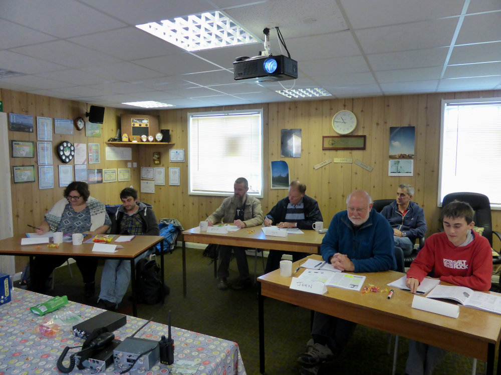
We’ve all been on the standard ‘death-by-PowerPoint’ type training courses, where you’re wishing the time to pass. Where an instructor will sit and read at you. Where they waffle for ten minutes, then say ‘but you don’t need to know that for the exam’. Those courses are so dull, aren’t they?
We’re not like that! OK, we use PowerPoint. It’s a great tool and it helps us not to go too far off topic. What we don’t do is sit down while we’re teaching. We are on our feet all of the time, moving around. We find that this helps to keep students engaged. We use humour as much as we can for the same reason, if the course is fun then learning is fun. If learning is fun then learning is easy.
We don’t read straight from the book, in fact we don’t even refer to it. We ask that students read through the book a few times before the course starts, mainly so that they become familiar with the terminology that we will be using. We then explain the contents of the book in our style, in our words, in our way. If there is something that a student doesn’t understand then we’ll take that on board. Rather than merely repeating what we’ve said, we are adept at flipping things around, looking at them from a different angle, using analogy or example to help explain. We can adapt to most people’s learning styles on the fly.
And we are the same at Intermediate level as well. I mentioned the Intermediate course being delivered over two non-consecutive weekends, with a weekend in between. Again, we tailor the training to suit the students. Exams have to be booked in advance, so they are booked for the third weekend. A majority of the training takes place over the first weekend, and is usually completed on the Sunday of the third weekend (exam day). That is all we’ve needed so far – three days. However, if students need extra time with us, we will know by the end of the first weekend (actually we’ll have a good idea a lot sooner than that). We have the Saturday of the third weekend available to us, and we are always available for the middle weekend as well. It’s never a case of rushing things through, it’s all about giving our students the best opportunity to pass the exam.
We don’t abandon you after you’ve passed the intermediate exam, there’s help available for you if you want to progress to the Full licence – the UK’s highest amateur radio licence level.
We do not run a Full licence course. There is a lot to learn, which means there’s a lot to deliver. There are only two of us and we are volunteers. But by the time you get to the stage of looking at the Full manual you should already have significant amounts of operating practice and be familiar with most of the principles. The Full is quite heavy on theory, not unreasonably given the privileges it affords you. We’ve found that most students are OK with learning from the book at this stage, but a fair few are not coming from a technical background and there are two sections where face-to-face training is the better option for almost everyone. To overcome this obstacle, we have put together two, one-day ‘primer’ sessions dealing with these topics.
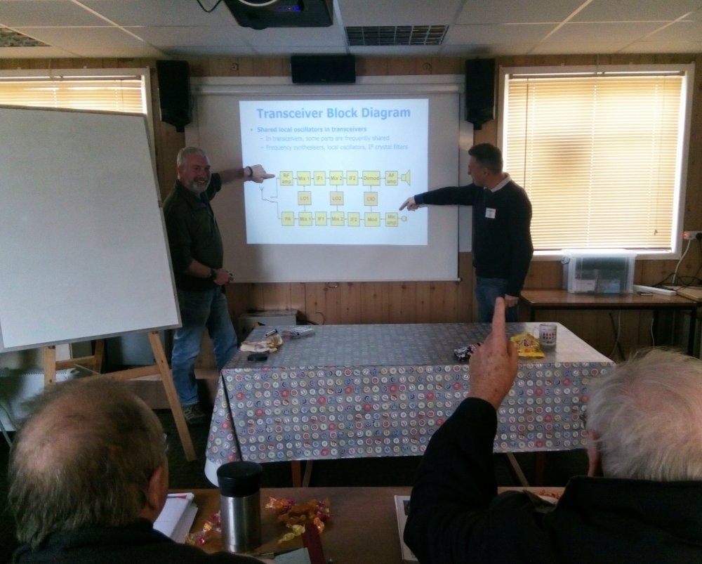
Clive does a one-day session on transmitters and receivers, covering everything in the book but explained more clearly, and with the help of further diagrams. Alan offers a one-day session covering maths (let’s face it, many of us haven’t used what we learned at school in many years) and electronics (one subject that really does need explaining). Neither of these primers is compulsory, they can be delivered in either order, you can do just one if that suits you.
So there you go, that’s what we do, and it’s why we get such great results too. So much so that people are willing to travel a fair distance to attend one of our training courses. FRARS is based just outside Wimborne in east Dorset. We have had students come to us from Devon, Hampshire, Buckinghamshire, one chap came down from Birmingham, and we even had a student from York – a 600 mile round trip for the weekend!
Unlike a lot of clubs, our premises has full internet with both Wi-Fi and optional LAN connections in our training room. All exams are done on-line now, with an instant indication at the end of the exam to show your result.
This article was written by Julian G3YGF for the K2UYH EME newsletter in March 2023. A PDF of the article can be downloaded here.
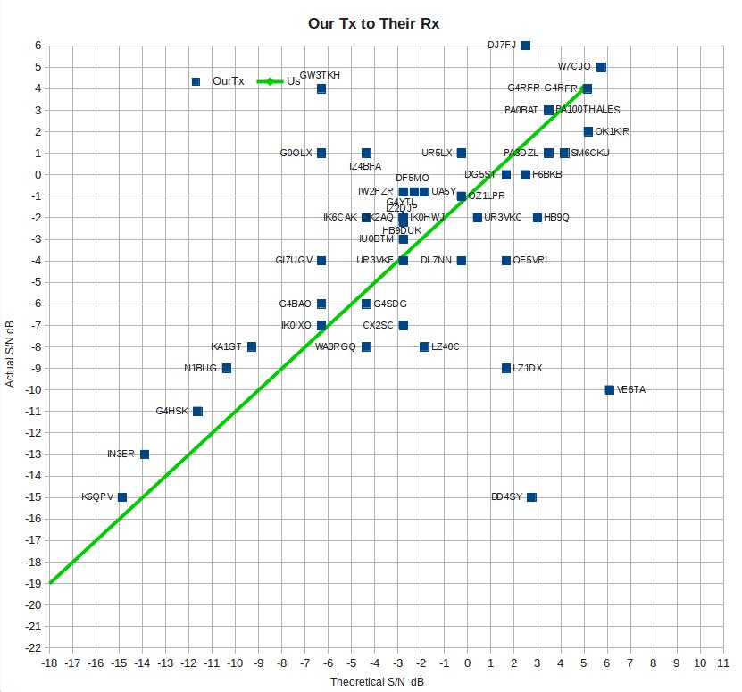
This analysis was suggested initially by M5RAO, a member of the FRARS group. Since Q65 generates a signal report automatically, here are plots of all the stations that we have worked or have heard us on Q65, on which we have data – if you only appear on one plot, it is because you only heard us, or we do not know your Tx EIRP.
The plots compare actual WSJT-X SNR reports, with calculated SNR derived from Tx power, Tx and Rx dish sizes obtained from HB9Q, nominal Rx Noise Figure, bandwidth (2500Hz), and path loss (minimum 288dB). The receive temperatures of other stations have been assumed to be 300K. Polarisation loss, if present, should be the same for both stations. Thus, if the data were perfect, all the points would lie on a straight line at 45 degrees. The Green lines are plots of our signals, received on our system for comparison, based on the strength we hear DL0SHF running 33W. Points to the upper/left of the line are overestimating the signal strength, points to the lower/right are underestimating it.
The first plot is “Their Tx to Our Rx” against Theoretical SNR. The plot shows a clear upper bound on the received SNR, and suggests that the maximum value of EIRPs of other stations are reasonably accurate.
The second plot is “Our Tx to Their Rx” against Theoretical SNR. There is a larger scatter on this one, and it suggests that, given that our Tx is fairly well characterised and the other station’s dish gain also occurs in the first plot, maybe other people’s WSJT reports or noise levels are more variable than we thought. On the plots, we/us etc refers to G4RFR.
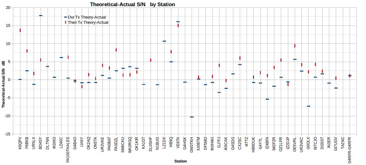
The third plot is “Theoretical SNR – Actual SNR for each direction by station”. This is the same data as before, plotted by station (in order of date worked, left to right). Most stations seem to be around the +2dB level, and so maybe the theoretical SNR is a bit high.
Reports have all been taken from the strongest transmission received, some over several QSOs, so most errors in dish pointing, and WSJT reporting on the first transmission heard, have been removed. It should be good to +/-1dB or so, but some errors will remain. The theoretical SNR should be good to a couple of dB.
Stations with a 10m dish, (HB9Q and VE6TA) have been reduced to 5m, as we have assumed the extra gain will not increase the signal strength much. The effective dish size of stations operating Circular Polarisation (eg HB9Q) has been reduced by 3dB to allow for the loss between CP and Linear, as the loss will affect both Tx and Rx.
Some stations, eg VE6TA, are on one side of the line with a similar offset in both plots 1 and 2; others, eg PA0THALES have a different offset in the two plots. Four or five stand out as significantly different. I would be interested to receive any updates to details put on HB9Q, or thoughts on the reason for these differences – eg dish gain, polarisation loss or noise temperature.
The club construction project for 2022 was an FT8 receiver for 20 m which would draw very little current and so could be left on 24 hours a day. Club members would then have a facility to do either monitoring or reverse beaconing up to PSK Reporter. The picture above is the prototype.
The project was designed to allow a complete build from scratch to happen and for all aspects of construction from electronic to mechanical construction to take place. It was designed to a budget of 30 GBP and to a simple schematic with very few coils needing to be wound.
The electronics were built on plain vero board and mounted in an aluminium die-cast box. This type of construction can be used with just about any system operating up to VHF frequencies and so the techniques can be applied to many types of construction in amateur radio. A picture of the inside of the box is shown below.
8 members of the club built the RX at the FRARS HQ near Wimborne and Poole. All of the builds were successful. Having access to test equipment at the club and members who had also built the RX almost certainly helped with the success of the construction project.
This is an example of one of the units that were built to the club’s design. This unit was built by Russ, G4CVX.
Everyone on the project really enjoyed the construction and I hope that a further club construction can be run again soon.
If you are interested in building this unit then please contact us here with a view to obtaining the construction details.
At the end of 2022 several FRARS members expressed an interest in getting a small group together to learn or improve CW (morse code).
CW is an excellent mode especially on HF where it allows much more potential for DX and conversational QSOs than modes like SSB.
It’s also just a satisfying mental exercise to learn the code and start making QSOs.
Nine people signed up for the group and Gareth, G0MFR volunteered to run the sessions with Tony, G3PFM there to offer expert advice where people were struggling.
We met at the club every Thursday evening starting in January 2023 and started introducing and practicing the characters over the winter months.
Several ‘students’ bought simple keys and built practice oscillators so when we got a few characters together we were soon sending to each other across the room.
As we progressed this developed to having QSOs with each other and we were ready to get on the air.
We started with operators that I knew who were very patient and soon we had everyone in the group with a QSO logged on 40 m CW.
People have subsequently progressed at different rates and we’re looking at running a refresher this winter.